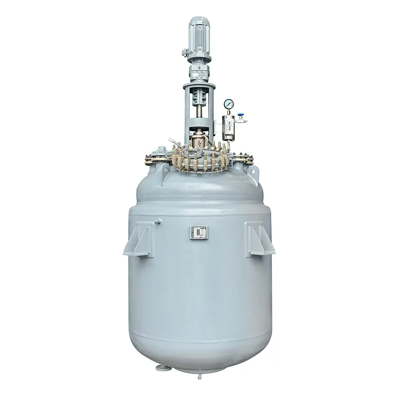
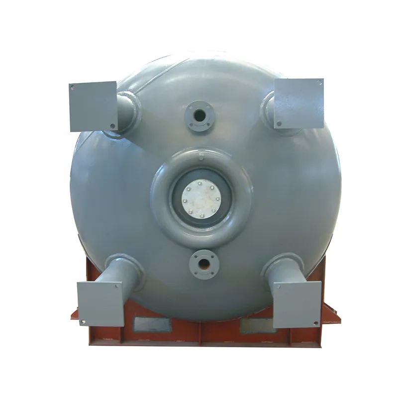
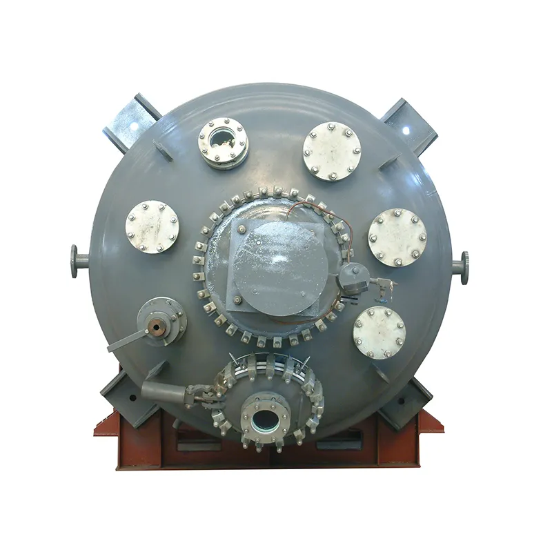
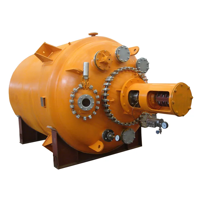
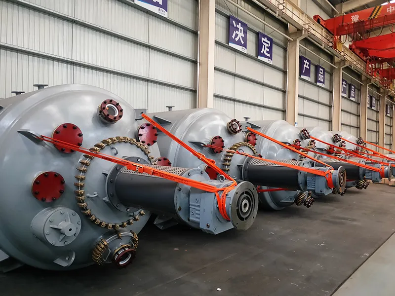
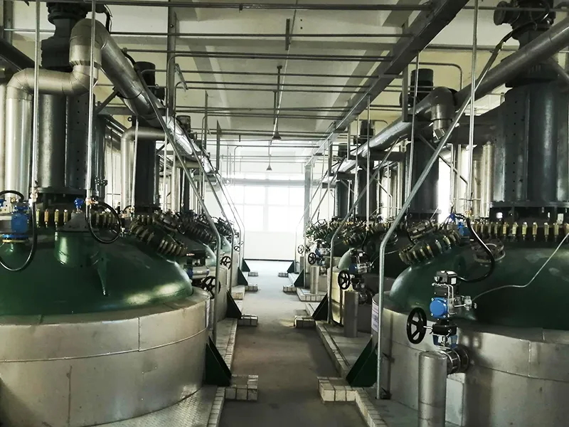
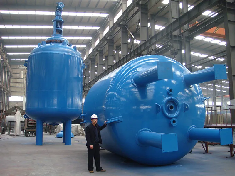
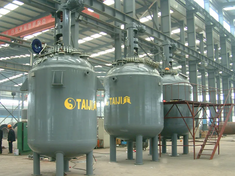
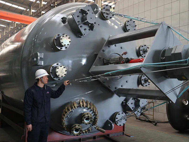
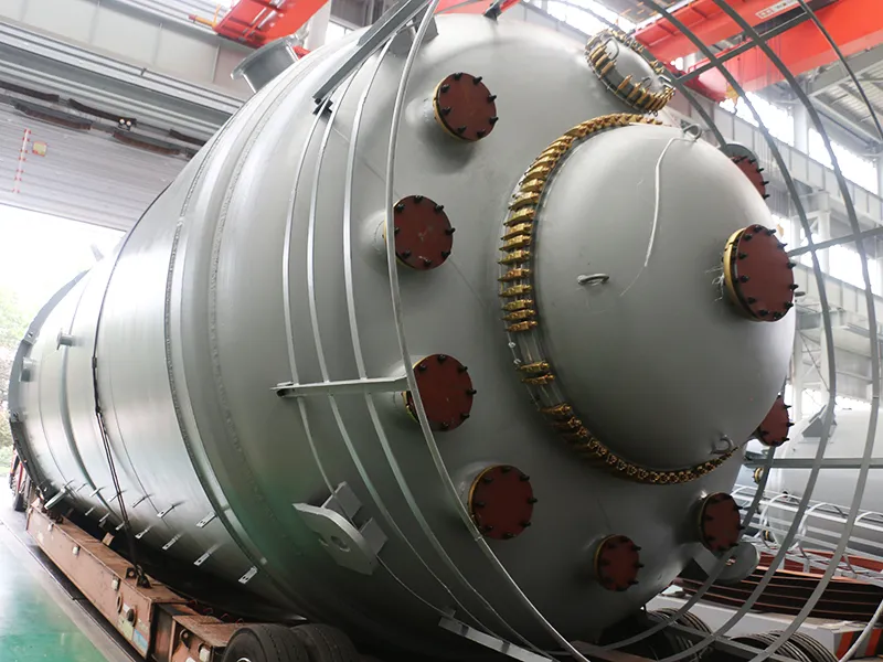
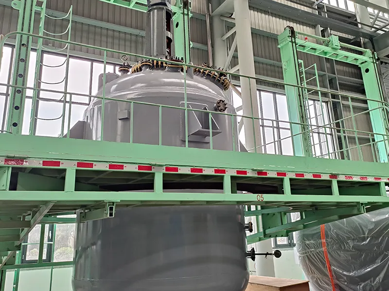
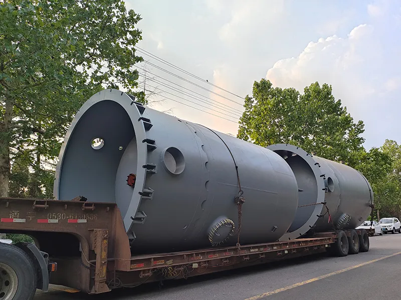
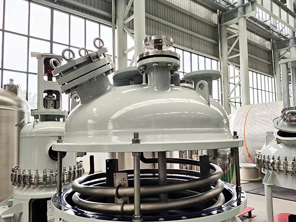
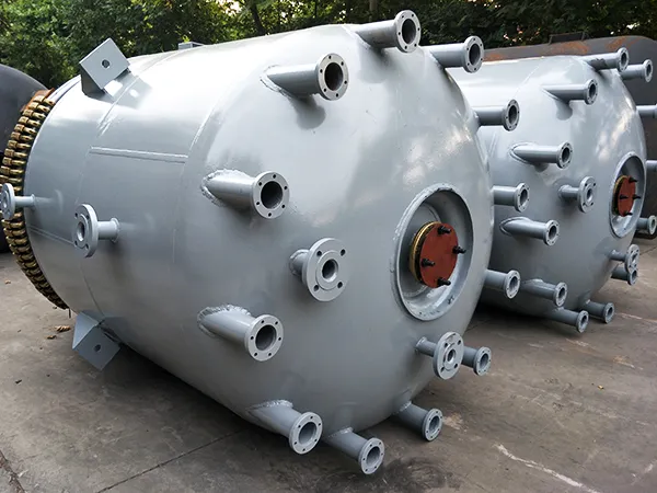
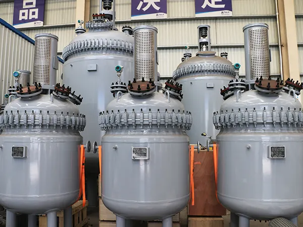
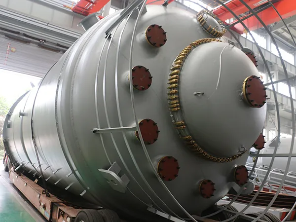
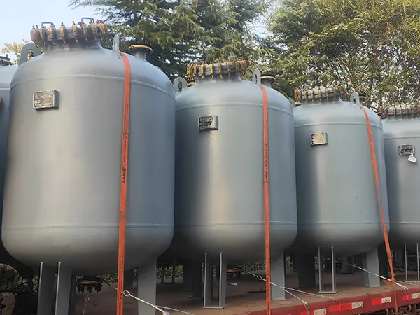
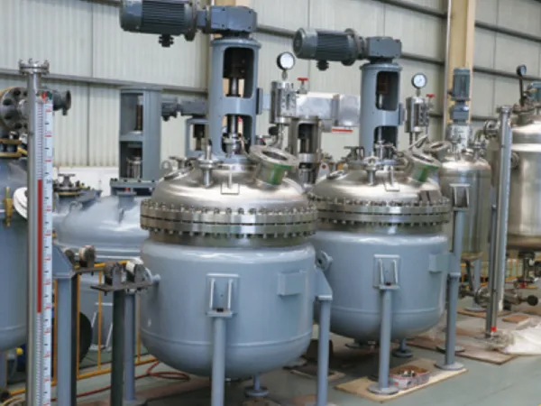
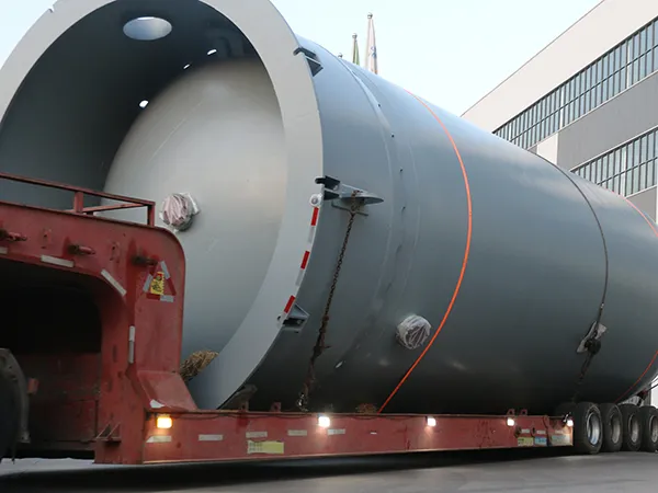
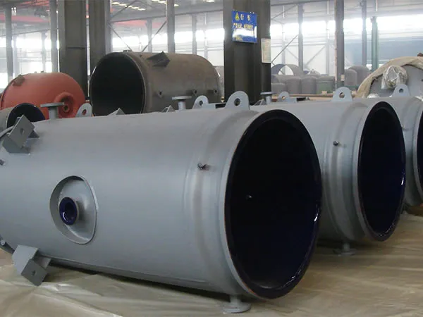
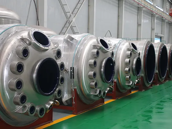
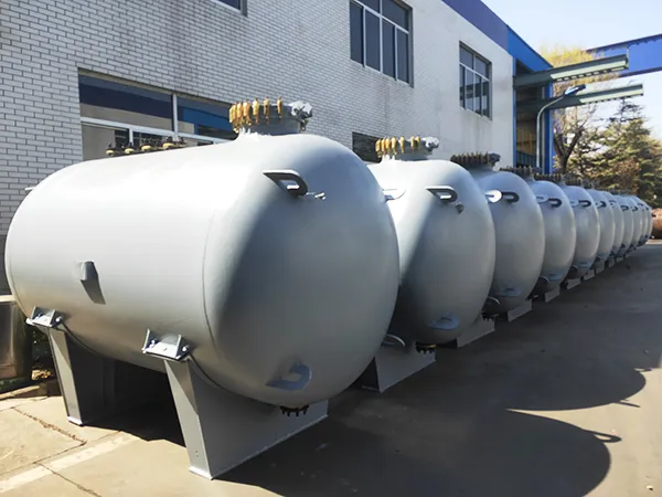
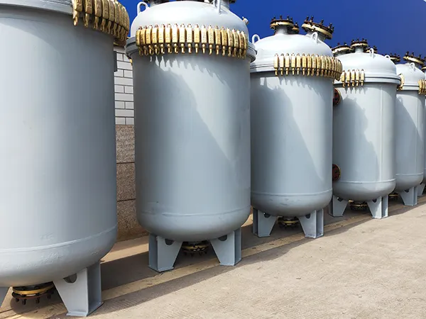
The F type glass lined reactor comes with a one-piece design that the cover and body can not be separated. Due to that, a manhole has to be designed on the head of the reactor to make it easy for operators to enter the reactor to carry out maintenance and parts replacement.
It is a large capacity industrial process reactor, suitable for large scale production environment.
Similar to the K-type reactor, this type of chemical reactor is manufactured using TJ09/TJ16/TJ21S high end enamel and skilled enameling process. This enables the glass lining to be remarkably corrosion resistant, impact resistant and temperature variation resistant, combined with less prone to fracture and high durability.
Taiji is able to design and manufacture non standard glass lined reactor to user's requirements.
Our F type glass lined steel reactor comes in complete specifications, including F1500L, F2000L, F3000L, F4000L, F5000L, F6300L, F8000L, F10000L, F12500L, F16000L, F20000L, F30000L, F40000L, F45000L, F50000L, F60000L, F70000L, F90000L, etc.
Request a Quote
Technical Parameters of the Glass-Lined Reactor
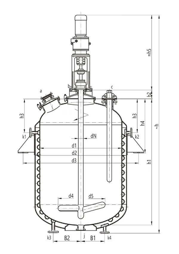
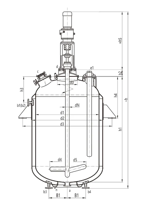
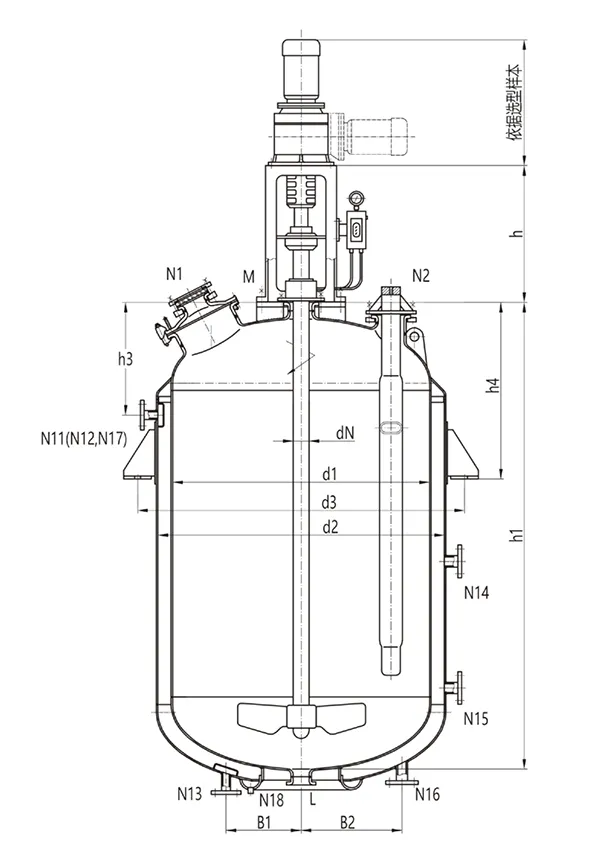
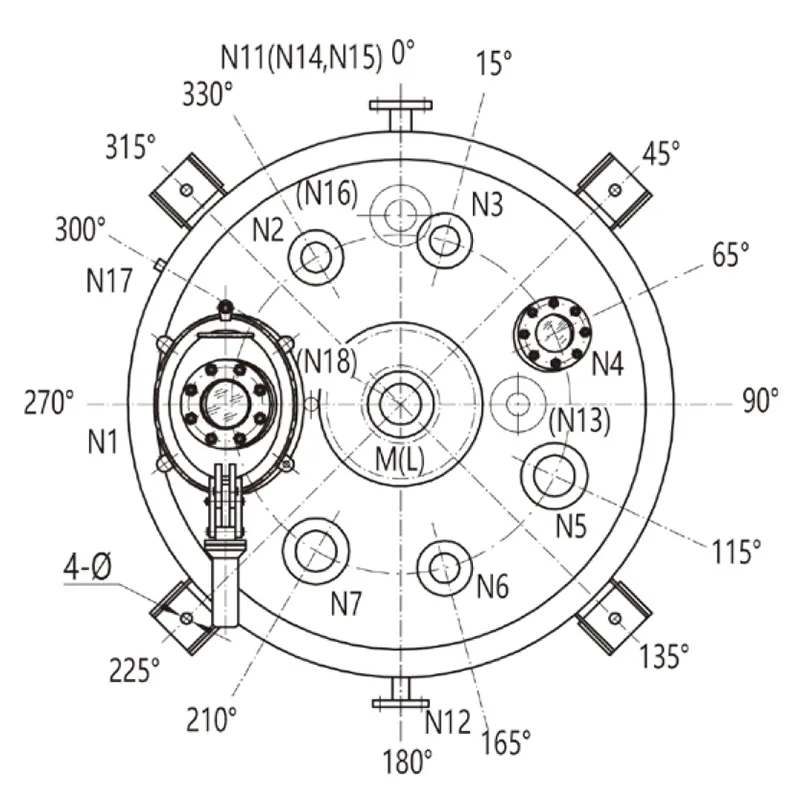
F1500L-F6300L Glass-Lined Reactor
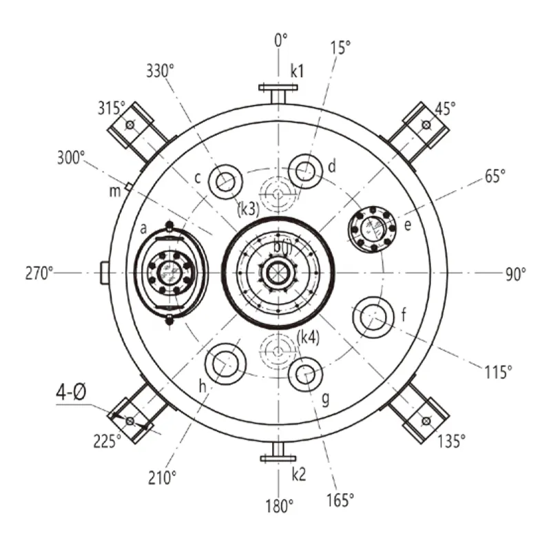
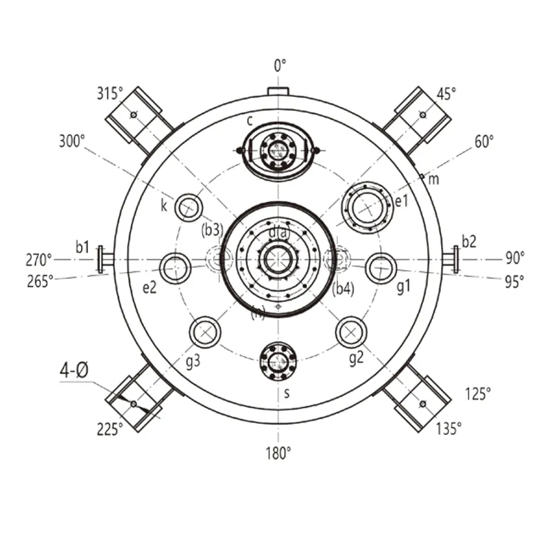
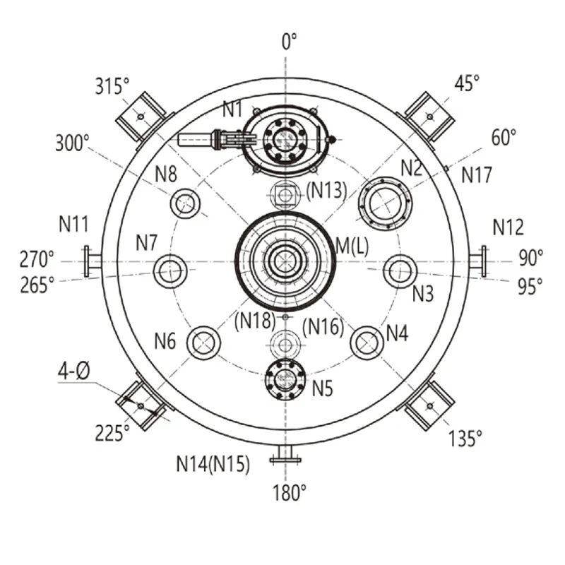
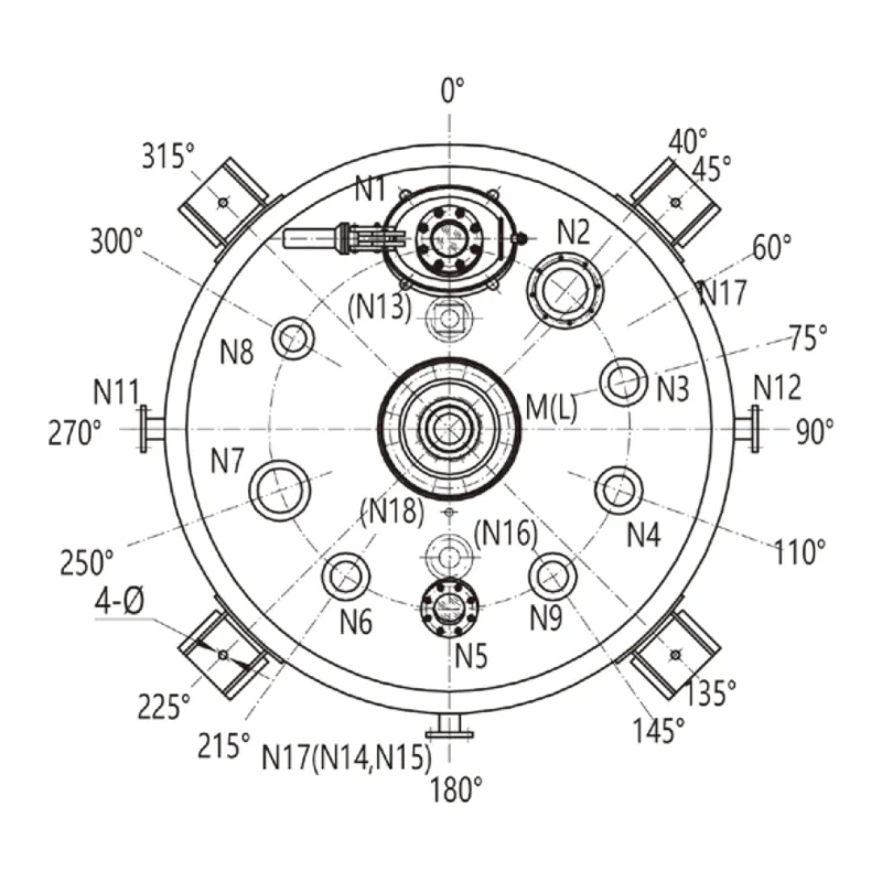
F1500L- F6300L Design Drawing (Plan View)
Internal Vessel
Jacket
Design Pressure (MPa)
0.4
0.6
Design Temperature ( ℃ )
-19 ~200
-19 ~200
Model
F 1500
F 2000
F 3000
F 4000
F 5000
F 6300
Nominal Capacity (L)
1500
2000
3000
4000
5000
6300
Total Capacity (L)
2020
2470
3860
4795
6040
6900
Calculated Capacity (Note 1) (L)
1990
2440
3830
4765
6016
6872
Jacket Capacity (L)
301
390
495
805
898
1015
Heat Exchange Area (m²)
5.92
7.31
9.98
12.44
14.06
16.36
Half-Pipe Coil Heat Exchange Area (m²)
2.5
3.5
4.3
6.0
7.2
8.5
Reference Weight (kg)
1975
2230
3300
3750
4570
5050
Dimensions (mm)
d1
1300
1300
1600
1600
1750
1750
d2
1450
1450
1750
1750
1900
1900
d3 (Note 2)
1915
1915
2221
2221
2412
2412
d4
680
680
720
720
720
720
d5
700
700
800
800
850
850
h1
1801
2136
2250
2730
2888
3244
h2
190
190
190
190
190
190
h3
725
725
700
700
750
750
h4
975
975
1060
1060
1200
1200
B1
315
315
315
315
350
350
B2
400
400
450
450
500
500
Φ
30
30
30
30
30
30
Vessel Nozzle DN (mm)
a
300x400
300x400
300x400
300x400
300x400
300x400
b
125
125
150
150
150
150
C
100
100
100
100
125
125
d
100
100
100
100
125
125
e
125
125
125
125
125
125
f
125
125
125
125
150
150
g
100
100
100
100
125
125
h
125
125
125
125
150
150
100
100
125
125
125
125
Jacket Nozzle DN (Note 3) (mm)
k1
40/50
40/50
65/50
65/50
65/50
65/50
k2
40
40
65
65
65
65
k3
40/50
40/50
65/50
65/50
65/50
65/50
k4
40
40
65
65
65
65
m
G3/8”
G3/8”
G3/8”
G3/8”
G3/8”
G3/8”
Drive (Note 4) (mm)
dN
80
80
95
95
95
95
h5
1580
1580
1680
1680
1680
1780
Notes
Calculated Capacity
Volume: Measures the capacity below the high neck flange. This does not include the volume taken up by the flange itself.
Support Options
The type of support used to hold the reactor can be specified by the customer when placing an order. If no preference is indicated, the default support type will be lugs attached to the exterior.
k1 and k3 Values
The dimensions k1 and k3 will vary depending on whether the reactor has a full jacket or half pipe heating/cooling system.
For a full jacket, use the values listed before the slash (/)
For half pipes, use the values after the slash (/)
Drive Device Parameters
Reference Only: The provided drive device parameters are for reference purposes.
Actual Selection: The final selection of the rack reducer type will be determined based on the specific requirements of the application.
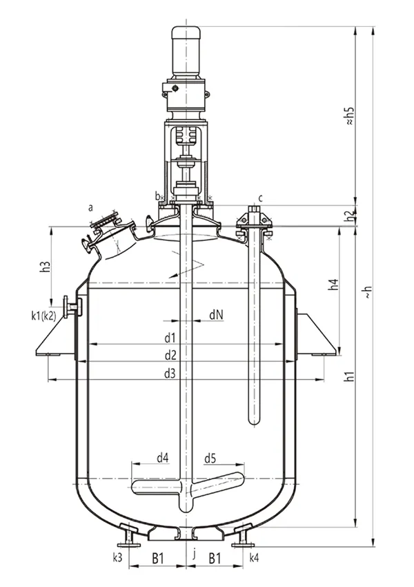
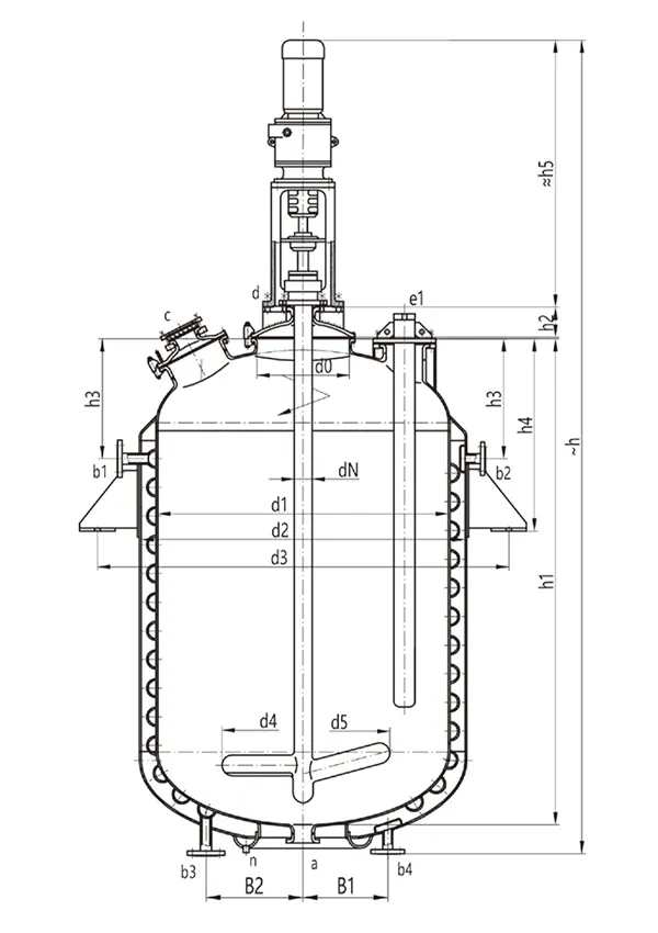
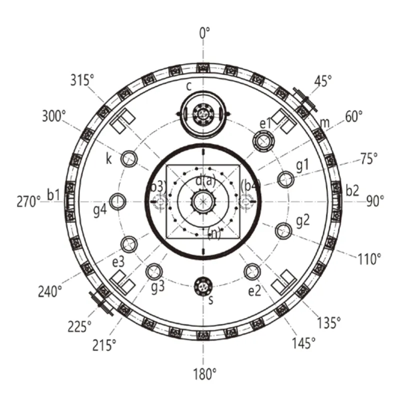
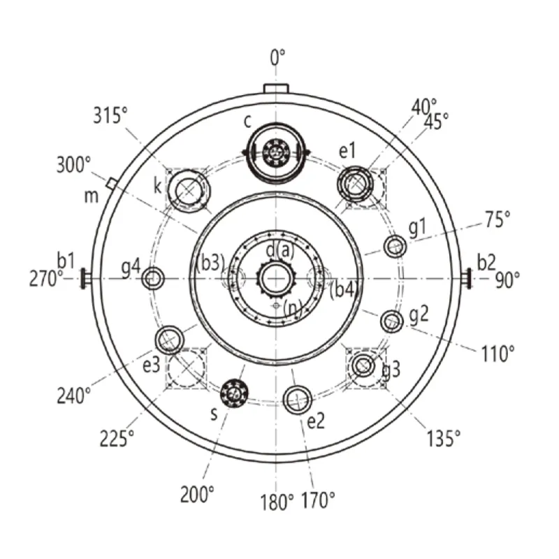
F8000-F20000L Glass-Lined Reactor
F8000L Design Drawing (Plan View)
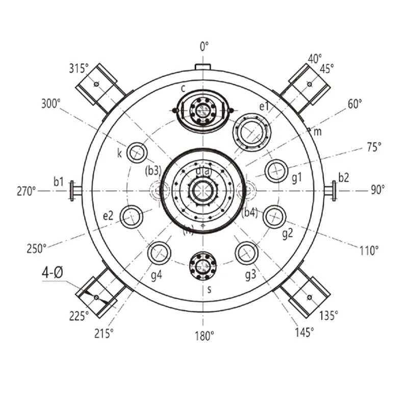
F10000L-20000L Design Drawing (Plan View)
Internal Vessel
Jacket
Design Pressure (MPa)
0.4
0.6
Design Temperature ( ℃ )
-19~200
-19~200
Model
F 8000
F 10000
F 12500
F 16000
F 20000
Nominal Capacity (L)
8000
10000
12500
16000
20000
Total Capacity (L)
9138
11757
13733
17491
21835
Calculated Capacity (Note 1) (L)
9110
11724
13700
17446
21790
Jacket Capacity (L)
1666
1940
2243
2551
2870
Heat Exchange Area (m²)
18.38
21.35
24.89
29.48
34.04
Half-Pipe Coil Heat Exchange Area (m²)
8.9
10.3
12.4
14.5
16.5
Reference Weight (kg)
6780
7670
9120
11300
13700
Dimensions (mm)
d0
800
800
800
800
900
d1
2000
2200
2200
2400
2600
d2
2200
2400
2400
2600
2800
d3 (Note 2)
2763
2964
2964
3238
3439
d4
880
980
980
980
1080
d5
1100
1200
1200
1200
1300
h1
3310
3533
4053
4346
4641
h2
210
210
210
210
210
h3
850
900
900
950
1000
h4
1250
1300
1300
1500
1550
h
5680
5890
6440
6770
7350
B1
400
470
470
470
470
B2
700
700
700
700
700
Φ
36
36
36
36
36
Vessel Nozzle DN (mm)
a
125
150
150
150
150
C
300x400
300x400
300x400
450
450
d
200
200
200
200
250
e1
200
200
200
200
200
e2
150
200
200
200
200
g1
150
150
150
150
150
g2
150
150
150
150
150
g3
150
150
150
150
150
g4
/
150
150
150
150
S
125
125
125
125
125
k
125
125
125
125
125
Jacket Nozzle DN (Note 3) (mm)
b1
65/65
80/65
80/65
100/65
100/65
b2
65
80
80
100
100
b3
65/65
80/65
80/65
100/65
100/65
b4
65
80
80
100
100
m
G3/4°
G3/4”
G3/4
G3/4”
G3/4*
n
G1/2"
G1/2”
G1/2”
G1/2”
G1/2”
Drive (Note 4) (mm)
dN
110
110
110
130
140
h5
1960
1960
1990
2020
2300
Notes
Calculated Capacity
Volume: Measures the capacity below the high neck flange. This does not include the volume taken up by the flange itself.
Support Options
The type of support used to hold the reactor can be specified by the customer when placing an order. If no preference is indicated, the default support type will be lugs attached to the exterior.
b1 and b3 Values
The dimensions b1 and b3 will vary depending on whether the reactor has a full jacket or half pipe heating/cooling system.
For a full jacket, use the values listed before the slash (/)
For half pipes, use the values after the slash (/)
Drive Device Parameters
Reference Only: The provided drive device parameters are for reference purposes.
Actual Selection: The final selection of the rack reducer type will be determined based on the specific requirements of the application.
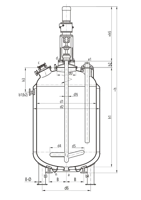
F30000-F90000 Glass-Lined Reactor
F30000L-50000L Design Drawing (Plan View)
F60000L-90000L Design Drawing (Plan View)
Model
F 30000
F 40000
F 45000
F 50000
F 60000
F 70000
F 90000
Nominal Capacity (L)
30000
40000
45000
50000
60000
70000
90000
Total Capacity (L)
33645
44900
51380
56470
64652
75290
93110
Calculated Capacity (Note 1) (L)
33500
44000
52180
55510
63641
74300
92110
Jacket Capacity (L)
3700
3800
4350
4520
5080
7350
9110
Heat Exchange Area (m²)
45.0
48.4
50.2
60
68.5
76.5
95.2
Reference Weight (kg)
20000
26520
29650
32155
36380
47950
61000
Dimensions (mm)
d0
1100
1600
1600
1750
1750
1750
1750
d1
3000
3600
3600
3800
3800
4000
4000
d2
3200
3800
3800
4000
4000
4200
4200
d4
1300
1400
1400
1600
1600
1600
1600
d5
1300
1400
1400
1600
1600
1600
1600
d6 (Note 2)
2300
2520
2520
2680
/
/
/
h1
5340
5000
5731
5611
6311
6692
8071
h2
260
609
609
647
667
667
667
h3
1150
1300
1300
1340
1340
1600
1600
h
8985
9040
9770
9790
10500
13000
14450
B
470
470
470
470
470
700
700
φ
24
30
30
30
/
/
/
Vessel Nozzle DN (mm)
a
150
150
150
150
150
150
150
C
450
450
450
450
450
450
450
d
250
250
250
250
250
300
300
e1
200
200
200
200
200
200
200
e2
200
200
200
200
200
200
200
e3
/
200
200
200
200
200
200
g1
150
150
150
150
150
150
150
g2
150
150
150
150
150
150
150
g3
150
150
150
150
150
150
150
g4
150
150
150
150
150
150
150
S
125
125
125
125
125
125
125
k
125
125
125
250
250
250
250
Jacket Nozzle DN (mm)
b1
100
125
125
125
125
125
125
b2
100
125
125
125
125
125
125
b3
100
125
125
125
125
125
125
b4
100
125
125
125
125
125
125
m
G3/4”
G3/4”
G3/4”
G3/4”
G3/4”
G3/4”
G3/4”
n
G1/2”
G1/2”
G1/2”
G1/2”
G1/2”
G1/2”
G1/2”
Drive (Note 3) (mm)
dN
160
160
160
180
200
240
273
h5
2570
2610
2610
2710
3420
3970
4170
Notes
Calculated Capacity
Volume: Measures the capacity below the high neck flange. This does not include the volume taken up by the flange itself.
Support Type
Customizable by the user. In the absence of a specific request, B-type support legs will be used. For specifications above F60000L, a skirt support is recommended.
Drive Device Parameters
These parameters are for reference only. The actual rack reducer type will be selected based on specific requirements.
Q630L-Q16000L Glass-Lined Reactor
Q630L-Q6300L Design Drawing (Plan View)
Q8000L Design Drawing (Plan View)
Q10000L-Q16000L Design Drawing (Plan View)
Internal Vessel
Jacket
Design Pressure (MPa)
-0.1/0.6/1.0
0.6
Design Temperature ( ℃ )
-19~200
-19~200
Model
Q630
Q1000
Q1500
Q2000
Q3000
Q4000
Q5000
Q6300
Q8000
Q10000
Q12500
Nominal Capacity (L)
630
1000
1500
2000
3000
4000
5000
6300
8000
10000
12500
16000
Total Capacity (L)
890
1470
2130
2575
3811
4780
6040
6900
9105
11719
13696
17491
Jacket Capacity (L)
147
206
301
390
495
805
898
1015
1666
1940
2243
2551
Heat Exchange Area (m²)
3.35
4.55
5.92
7.31
9.98
12.44
14.06
16.36
18.38
21.35
24.89
29.48
Reference Weight (kg)
1055
1865
1963
2175
3205
3522
4580
5060
6718
7670
9101
10954
Dimensions (mm)
d1
1000
1200
1300
1300
1600
1600
1750
1750
2000
2200
2200
2400
d2
1100
1300
1450
1450
1750
1750
1900
1900
2200
2400
2400
2600
d3 (Note 1)
1276
1477
1655
1655
1956
1956
2152
2152
2452
2703
2703
2908
h1
1385
1560
1766
2131
2250
2730
2888
3244
3320
3543
4063
4356
h3
595
650
699
699
700
700
750
750
860
910
910
960
h4
815
910
940
940
1060
1060
1200
1200
1210
1310
1310
1410
B1
400
400
400
400
400
400
400
400
400
470
470
470
B2
/
/
510
510
510
510
510
510
510
550
550
550
Φ
30
30
30
30
30
30
30
30
30
36
36
36
Vessel Nozzle DN (mm)
M
125
125
125
125
150
150
150
150
200
200
200
200
L
100
100
100
100
125
125
125
125
125
150
150
150
N1
300X400
300X400
300X400
300X400
350X450
350X450
350X450
350X450
500
500
500
600
N2
100
125
125
125
150
150
200
200
200
200
200
200
N3
100
100
100
100
100
100
125
125
150
150
150
150
N4
100
100
125
125
125
125
125
125
150
150
150
150
N5
100
125
125
125
125
125
150
150
125
125
125
125
N6
100
100
100
100
100
100
125
125
150
150
150
150
N7
100
100
125
125
125
125
125
125
150
200
200
200
N8
/
/
/
/
/
/
/
/
125
125
125
125
N9
/
/
/
/
/
/
/
/
/
150
150
150
Jacket Nozzle DN (mm)
N11
32
32
40
40
50
50
65
65
65
80
80
100
N12
32
32
40
40
50
50
65
65
65
80
80
100
N13
32
32
40
40
50
50
65
65
65
80
80
100
N14
/
/
/
/
65
65
65
80
80
100
N15
/
/
50
50
65
65
65
65
65
80
80
100
N16
/
/
50
50
65
65
65
65
65
80
80
100
N17
G3/8”
G3/8”
G3/8”
G3/8”
G3/8”
G3/8”
G3/8”
G3/8”
G3/4”
G3/4”
G3/4”
G3/4”
N18
G1/2”
G1/2”
G1/2”
G1/2”
G1/2”
G1/2”
G1/2”
G1/2”
G1/2”
G1/2”
G1/2”
G1/2”
Drive (mm)
dN
65
80
80
80
95
95
95
95
110
110
110
130
h
680
720
720
720
785
785
785
785
840
840
840
820
Notes Support Options: The type of support used to hold the reactor can be specified by the customer when placing an order. If no preference is indicated, the default support type will be lugs attached to the exterior.
What are the differences between K type and F type glass-lined reactors?
Unlike the K-type glass-lined reactor, the F-type glass-lined reactor is designed with integrated vessel head and vessel body. A manway is provided on top for internal inspection and component replacement.
The K-type glass-lined reactors, instead, are designed with removable head structure. The vessel head is connected to the vessel body with gasket and clamps for easy disassembly and maintenance, and more accessible agitation system.
The K-type glass-lined reactors are available in capacities from 50 to 16,000 L, which are more suitable for small- and medium-capacity production; the F-type glass-lined reactors are designed for medium- and large-scale industrial production and are available in capacities from 1,500 to 90,000 L. Therefore, the F-type glass-lined reactors are more suitable for high-volume production in chemical, pharmaceutical, and agrochemical industries.
Both types of glass-lined reactors can be configured with agitation system, heat transfer system and related components. Specific models should be selected according to production capacity, maintenance requirements, agitation requirements and process conditions.
Applications
The glass-lined reactor (F-type) is primarily used for medium- and large-scale industrial reaction processes during the production of pharmaceuticals, pesticides and agrochemicals, fine chemicals, basic chemicals, dyes and pigments, and other chemical products.
Depending on the specific materials and process conditions, the glass-lined reactor can be used for chemical synthesis, esterification, condensation, hydrolysis, polymerization, neutralization, chlorination, and other reaction, mixing, and temperature-control processes involving corrosive materials.
Whether the glass-lined equipment can be used for a specific process should be determined according to material composition, concentration, temperature, pressure and actual reaction conditions.